STM32F103 "Hello World" Part3
Purpose
本篇實際操作STM32CubeMX去生成initialization code
Development board在Part1介紹
預計demo功能為USART, GPIO, HSE
USART dump "Hello World",
GPIO toggle LED,
使用Oscillator -> PLL -> 72MHz, 為system clock
STM32CubeMX Version 4.25
Pin assignment
USART1 : RX(PA_10), TX(PA_9)
LED : PC_13
External Oscillator : OSC_IN(PD_0) & OSC_OUT(PD_1)
2-Wire Serial Debug : SWDIO(PA_13) & SWCLK(PA_14)
Step by step
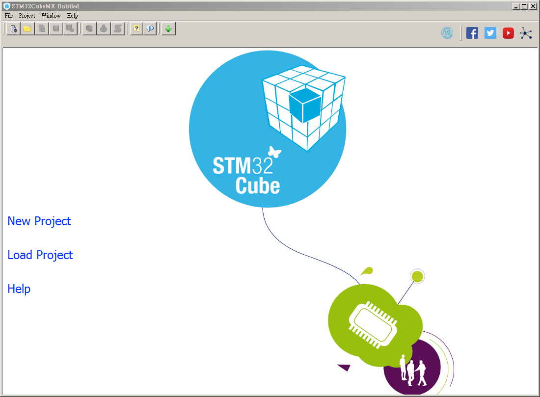
Step 1. click New Project
Step 2. 選擇MCU型號, 可透過下方Filter Search挑選MCU, 或直接Part Number Search輸入型號, 找到後連點兩次進去主畫面

Step 3. 主畫面
在Pinout分頁中可設定開啟或關閉各項Peripherals, 右邊為Chip View, 檢查Pin使用情況

Step 4. 設定各Peripherals, 如下圖左
本篇實際操作STM32CubeMX去生成initialization code
Development board在Part1介紹
預計demo功能為USART, GPIO, HSE
USART dump "Hello World",
GPIO toggle LED,
使用Oscillator -> PLL -> 72MHz, 為system clock
STM32CubeMX Version 4.25
Pin assignment
USART1 : RX(PA_10), TX(PA_9)
LED : PC_13
External Oscillator : OSC_IN(PD_0) & OSC_OUT(PD_1)
2-Wire Serial Debug : SWDIO(PA_13) & SWCLK(PA_14)
Step by step
Step 1. click New Project
Step 2. 選擇MCU型號, 可透過下方Filter Search挑選MCU, 或直接Part Number Search輸入型號, 找到後連點兩次進去主畫面
Step 3. 主畫面
在Pinout分頁中可設定開啟或關閉各項Peripherals, 右邊為Chip View, 檢查Pin使用情況
Step 4. 設定各Peripherals, 如下圖左
- RCC config
- SYS config
- USART1 config
選擇Mode為Asynchronous
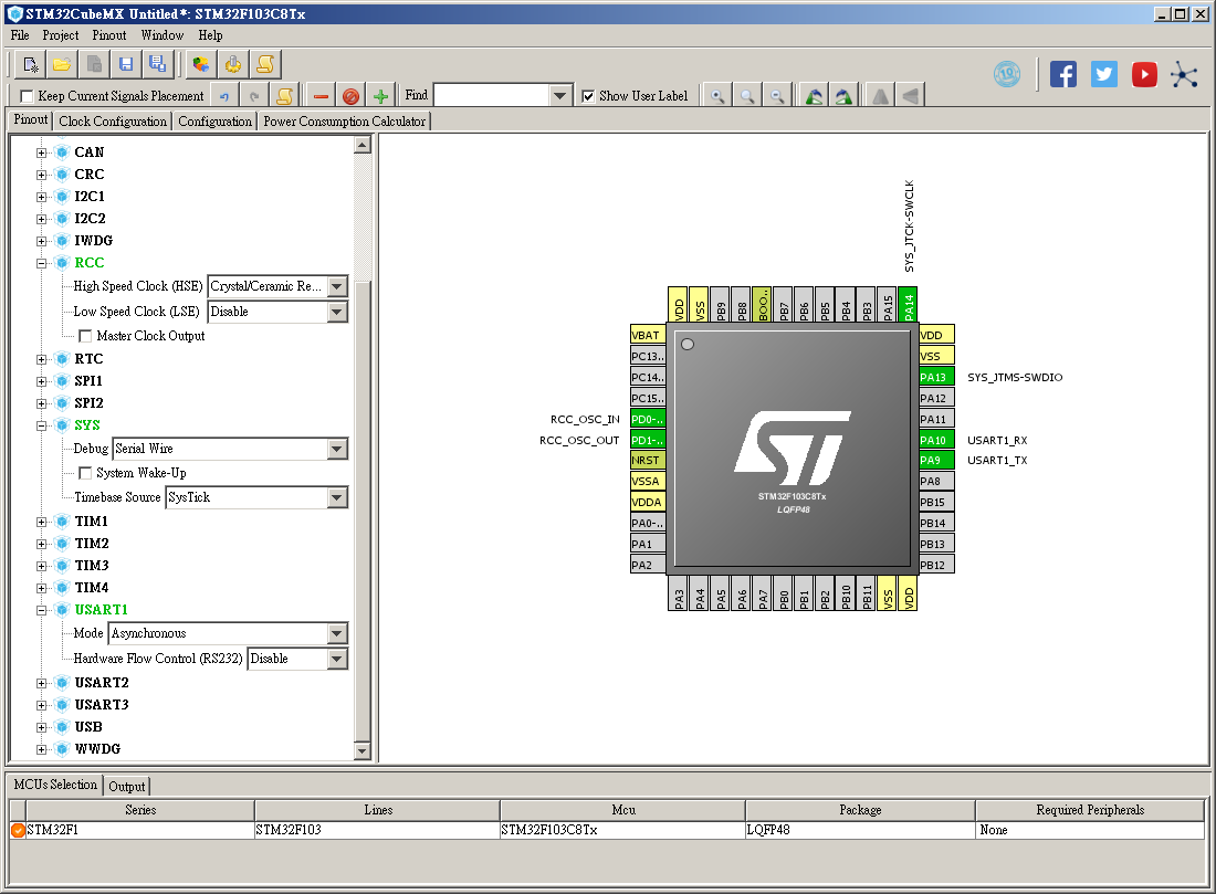

設定好後, 右邊Chip View顯示相對應的Pin assignment
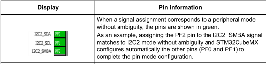
被設定過的Peripherals與Pin會以不同顏色表示
於官方TRM (UM1718)有詳細定義, 下方列出常見define

Step 5. 切換至Clock Configuration可看到Clock Tree
使用外部8MHz Oscillator, 經倍頻到72MHz (SYS_CLK max.), 配置如下圖
以HSE為PLL Source -> PLLMul*9 -> System Clock Mux選擇PLLCLK
如設定出現錯誤, 框底以紅色警示

說明

Step 6. 切換至Configuration頁面, 可詳細設定Periphals
 USART1
Baud rate = 115200bps
 GPIO
GPIO
使用自定義名稱(User Label), 於Pinout將顯示自定義接腳名稱


Step 7. Project Setting
Menu -> Project -> Setting
相關設定供參考, 依喜好設定
官方TRM 5.8章Project Settings window


Step 8. Generate Code
Menu -> Project -> Generate Code

STM32CubeMX操作流程如上述, 接下來轉至Keil進行coding!
Step 9. Open Project
以Keil開啟後, project tree如下
main.c 位於./Application/User, 主要執行system clock configuration, HAL peripherals initialization, user code
stm32f1xx_it.c 為interrupt handler

在STM32CubeMX產生的專案裡, 可看到許多USER CODE BEGIN & END的註解, 請將code撰寫於BEGIN & END的範圍內, 避免re-generate code時造成竭盡心力撰寫的code遺失
Step 10. Development code
設計功能為間隔1sec 透過UART 發送"Hello World\r\n", 同時PC13 LED toggle
UART 發送可分為polling, interrupt, DMA, 這裡以polling 為範例
由於選擇的是USART1 - asynchronous mode, 以STM32F103C8T6 為例, PA9 PA10 為USART1 interface, 分別是UART_TX, UART_RX
上述設計功能以下列3個API完成
HAL_UART_Driver operation functions

HAL_GPIO_Driver operation functions

HAL_System_Driver operation functions

於USER CODE BEGIN PV & USER CODE END PV貼以下code
於while loop 中直接call printf 即可
Resources
UM1718
http://www.st.com/resource/en/user_manual/dm00104712.pdf
STM32CubeMX介绍、下载与安装
https://blog.csdn.net/ybhuangfugui/article/details/52225736
STM32CubeMX新建工程+基本IO配置过程
https://blog.csdn.net/ybhuangfugui/article/details/52281260
STM32CubeMX系列教程
http://www.waveshare.net/study/portal.php?mod=list&catid=38
- GPIO config
設定好後, 右邊Chip View顯示相對應的Pin assignment
被設定過的Peripherals與Pin會以不同顏色表示
於官方TRM (UM1718)有詳細定義, 下方列出常見define
使用外部8MHz Oscillator, 經倍頻到72MHz (SYS_CLK max.), 配置如下圖
以HSE為PLL Source -> PLLMul*9 -> System Clock Mux選擇PLLCLK
如設定出現錯誤, 框底以紅色警示
說明
Step 6. 切換至Configuration頁面, 可詳細設定Periphals
Baud rate = 115200bps
使用自定義名稱(User Label), 於Pinout將顯示自定義接腳名稱
Step 7. Project Setting
Menu -> Project -> Setting
相關設定供參考, 依喜好設定
官方TRM 5.8章Project Settings window
- Project頁面
- Code Generator頁面
選擇Copy only the necessary library files
只複製有需要的Library, 第一項會將Middleware Level的Library也一併放進Project, 容量過大Step 8. Generate Code
Menu -> Project -> Generate Code
生成完Initialization code, 跳出一對話框, 如下圖
STM32CubeMX操作流程如上述, 接下來轉至Keil進行coding!
Step 9. Open Project
以Keil開啟後, project tree如下
main.c 位於./Application/User, 主要執行system clock configuration, HAL peripherals initialization, user code
stm32f1xx_it.c 為interrupt handler
在STM32CubeMX產生的專案裡, 可看到許多USER CODE BEGIN & END的註解, 請將code撰寫於BEGIN & END的範圍內, 避免re-generate code時造成竭盡心力撰寫的code遺失
  /* USER CODE BEGIN WHILE */
  while (1)
  {

  /* USER CODE END WHILE */
Step 10. Development code
設計功能為間隔1sec 透過UART 發送"Hello World\r\n", 同時PC13 LED toggle
UART 發送可分為polling, interrupt, DMA, 這裡以polling 為範例
由於選擇的是USART1 - asynchronous mode, 以STM32F103C8T6 為例, PA9 PA10 為USART1 interface, 分別是UART_TX, UART_RX
上述設計功能以下列3個API完成
HAL_UART_Driver operation functions
HAL_GPIO_Driver operation functions
HAL_System_Driver operation functions
- Transmit the string by using HAL_UART_Transmit
int main(void)
{
    /* USER CODE BEGIN 1 */
    char str[] = "Hello World\r\n";
    /* USER CODE END 1 */

    /* MCU Configuration----------------------------------------------------------*/

    /* Reset of all peripherals, Initializes the Flash interface and the Systick. */
    HAL_Init();

    /* USER CODE BEGIN Init */

    /* USER CODE END Init */

    /* Configure the system clock */
    SystemClock_Config();

    /* USER CODE BEGIN SysInit */

    /* USER CODE END SysInit */

    /* Initialize all configured peripherals */
    MX_GPIO_Init();
    MX_USART1_UART_Init();
    /* USER CODE BEGIN 2 */

    /* USER CODE END 2 */

    /* Infinite loop */
    /* USER CODE BEGIN WHILE */
    while (1)
    {
        if (HAL_UART_Transmit(&huart1, (uint8_t *)str, sizeof(str), 0xFFFF) != HAL_OK) {
            Error_Handler();
        }
        HAL_GPIO_Toggle(LED_BUILTIN_GPIO_Port, LED_BUILTIN_Pin);
        HAL_Delay(1000);
        /* USER CODE END WHILE */

        /* USER CODE BEGIN 3 */

    }
    /* USER CODE END 3 */

}
- 以sprintf function增加靈活性, 可快速字串格式設定
int main(void)
{
    /* USER CODE BEGIN 1 */
    char str[100];
    uint32_t i;
    /* USER CODE END 1 */

    /* MCU Configuration----------------------------------------------------------*/

    /* Reset of all peripherals, Initializes the Flash interface and the Systick. */
    HAL_Init();

    /* USER CODE BEGIN Init */

    /* USER CODE END Init */

    /* Configure the system clock */
    SystemClock_Config();

    /* USER CODE BEGIN SysInit */

    /* USER CODE END SysInit */

    /* Initialize all configured peripherals */
    MX_GPIO_Init();
    MX_USART1_UART_Init();
    /* USER CODE BEGIN 2 */

    /* USER CODE END 2 */

    /* Infinite loop */
    /* USER CODE BEGIN WHILE */
    i = 0;
    while (1)
    {
        sprintf(str, "Hello World, CNT: %d\r\n", i++);
        if (HAL_UART_Transmit(&huart1, (uint8_t *)str, sizeof(str), 0xFFFF) != HAL_OK) {
            Error_Handler();
        }
        /* USER CODE END WHILE */

        /* USER CODE BEGIN 3 */
        HAL_GPIO_TogglePin(LED_BUILTIN_GPIO_Port, LED_BUILTIN_Pin);
        HAL_Delay(1000);
    }
    /* USER CODE END 3 */

}
- Implement Print function
於USER CODE BEGIN PV & USER CODE END PV貼以下code
/* USER CODE BEGIN PV */
/* Private variables ---------------------------------------------------------*/

#ifdef __GNUC__
/* With GCC, small printf (option LD Linker->Libraries->Small printf
set to 'Yes') calls __io_putchar() */
#define PUTCHAR_PROTOTYPE int __io_putchar(int ch)
#else
#define PUTCHAR_PROTOTYPE int fputc(int ch, FILE *f)
#endif /* __GNUC__ */
PUTCHAR_PROTOTYPE
{
    /* Place your implementation of fputc here */
    /* e.g. write a character to the USART1 and Loop until the end of transmission */
    HAL_UART_Transmit(&huart1, (uint8_t *)&ch, 1, 0xFFFF);

return ch;
}

/* USER CODE END PV */
於while loop 中直接call printf 即可
    /* Infinite loop */
    /* USER CODE BEGIN WHILE */
    i = 0;
    while (1)
    {
        printf("Hello World, CNT: %d\r\n", i++);
        /* USER CODE END WHILE */

        /* USER CODE BEGIN 3 */
        HAL_GPIO_TogglePin(LED_BUILTIN_GPIO_Port, LED_BUILTIN_Pin);
        HAL_Delay(1000);
    }
    /* USER CODE END 3 */
Resources
UM1718
http://www.st.com/resource/en/user_manual/dm00104712.pdf
STM32CubeMX介绍、下载与安装
https://blog.csdn.net/ybhuangfugui/article/details/52225736
STM32CubeMX新建工程+基本IO配置过程
https://blog.csdn.net/ybhuangfugui/article/details/52281260
STM32CubeMX系列教程
http://www.waveshare.net/study/portal.php?mod=list&catid=38
留言
張貼留言